Pages

Saturday, October 28, 2023

Prinsip Kerja Mesin Diesel

    Diesel merupakan salah satu mesin konvensi energi yang terjadi secara internal combustion dengan fluida kerja berupa udara yang tidak mengalami perubahan fasa saat proses masuk, terjadinya pembakaran hingga keluar sebagai udara buang melalui cerobong exhaust. Merangkum dari buku Thermodynamic karangan Yunus Cengel yang sering jadi acuan beberapa mata kuliah (bab 9  halaman 488).

    Salah satu jenis konversi energi dalam mesin pembakaran berjenis reciprocating atau bersifat bolak balik memiliki prinsip kerja ketika bahan bakar diumpankan kedalam ruang bakar dan tercampur dengan udara kemudian terkompresi energi (kimia) menjadi panas yang dapat menggerakkan secara mekanis suatu piston. Perubahan energi kimia (pembakaran) menjadi energi kinetik inilah yang dimanfaatkan untuk konversi energi yang dapat dimanfaatkan dalam proses berikutnya, apakah itu menjadi putaran roda ataupun menjadi penggerak generator untuk menghasilkan energi listrik. 

    Mesin diesel adalah salah satu jenis mesin konversi energi dengan prinsip recripocating secara pembakaran internal. Sedangkan fluida kerjanya adalah udara yang tidak mengalami peubahan fasa dan hanya mengalami perubahan secara volume maupun tekananya. Secara sederhana prinsip kerja mesin diesel dalam PLTD dapat dijelaskan sebagai berikut; perta bahan bakar dalam tanki bahan bakar misal MFO, HSD mapun B30 yang dialirkan dari daily tank dipompakan kedalam nozzle yang berfungsi sebagai pengabut yang menerima injeksi bahan bakar bertekanan tinggi dan temperature juga naik seiring kenaikan tekanan fluida. Supplai udara kedalam diesel dialirkan dari tanki udara melalui air intake system kemudian dialirkan melalui turbocharger untuk lebih mengefisiensikan dengan meningkatkan tekanan udara yang masuk. Turbocharger sendiri bekerja seperti mesin kompresi sentrifugal yang mendapat daya turbinnya dari gas buang. Tekanan yang dicapai udara mencapai 500 psi (34 bar) dan temperature 600 degC kemudian dialirkan ke ruang bakar secara simultan dengan aliran bahan bakar. Udara bertekanan dan temperatur tinggi yang masuk dalam silinder di ruang bakar akan membantu terjadinya self ignition dari bahan bakar ketika disemprotkan sehingga terjadi “ledakan” sehingga dapat menggerakkan torak yang dihubungkan dengan poros engkol oleh batang penggerak dan menyebabkan pergerakan secara rotasi poros rotor (generator) dan dikonversikan menjadi energi listrik.

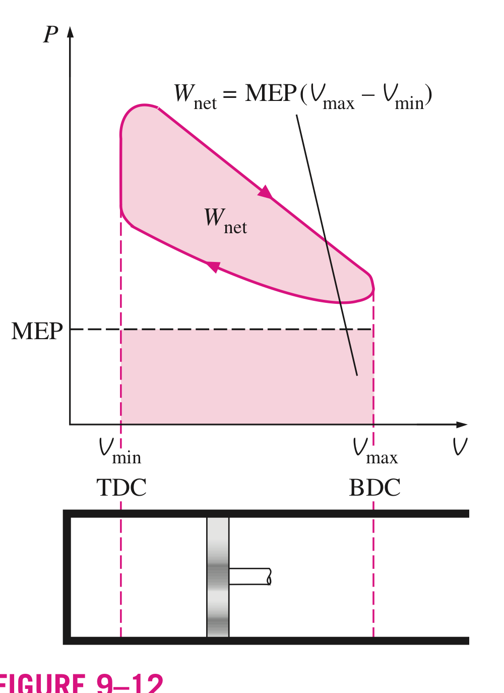
    Mesin diesel menggunakan prinsip reciprocating memiliki komponen utama yang berperan dalam mekanisme konversi energi seperti pada gambar berikut;

.
Terdapat dua posisi piston berupa TDC atau Top Dead Center dan BDC Bottom Dead Center. TDC menunjukkan posisi piston ketika berada diatas dan memiliki luasan dan volume paling sedikit kebalikannya dengan BDC yang memiliki besaran volume yang paling besar. Jarak antara TDC dan BDC yang juga jarak yang dilalui piston ketika terjadi mekanisme reciprocating dikenal dengan stroke. Bagian berikutnya adalah bore yang merupakan diameter piston. Suplai campuran udara dan bahan bakar ke ruang bakar (cylinder) memlaui intake valve dan hasil pembakaran dibuang melalui exhaust valve. Rasio kompresi ditunjukkan dengan perbandingan maximum volume dengan minimum (clearence) volume;
Energi yang dihasilkan (net work) menggunakan pendekatan yang melibatkan formula Mean Effective Pressure (MEP) dengan memperhitungkan area piston dan jarak stroke dari piston. 
                Wnet = MEP x Piston Area x Stroke = MEP x Displacement Volume
MEP bisa digunakan sebagai parameter pembanding untuk mengukur tingkat perfomance mesin dan semakin besar MEP menunjukkan energi yang dihasilkan lebih besar dan performa lebih bagus (secara ideal). 

Wnet menunjukkan luasan dari jarak Vmax ke Vmin dan seberapa besar mean effective pressure ditunjukkan dengan gambar dan rumus diatas.
_|Berlanjut ke siklus Otto|_


Sunday, August 7, 2022

Numerical Study Of Gas Mixing Effect On Block 3 & 4 Muara Tawar’s Gas Turbine Combustion Stability

DOI: 10.1007/978-981-19-1581-9_33

Abstract. Gas turbine operation’s disturbances related to combustion that lead to flame instability greatly influenced by the setting of fuel and air which is adjusted according to gas availability during commissioning. Meanwhile, gas turbine must be able to operate using a variety of natural gases or its mixing depending on the system and gas availability. This study presents the numerical simulation to obtain the combustor’s characteristics by analysis the flame stabilization, temperature distribution, and Nox emission by varying the fuel gas sourced and air mass flow. The numerical analysis has shown that fuel with higher CH4 contains will tend the ombustion become more unstableand and stabilized by the inner recirculation zone. The more excess air also provide more stable combustion as flame lenght decrease, but too much excess air will decrease the total temperature. NOx emission produced from the combustion which produce higher temperature from methane and excess air effect. The recommendation of the research results is to provide a limitation of the composition of the gas mixing and the fuel air ration to obtain the combustion stability. The results of the study simulate that it is possible to use three condition of fuel gas in combustion system.


Keywords: gas composition, stability, temperature distribution, emission NOx, excess
air.

1. Introduction

Power plants managed by PT PJB UP Muara Tawar operates as peak load (peaker) with periodic
start-stop operation. Block 3 and 4 operate V 94.2 Siemens’s type gas turbines. Natural gas as gas turbine
fuel comes from 3 different suppliers, Nusantara Regas (NR), Pertamina EP (PEP) and PGN with their
chemical composition values. Gas turbine operation’s disturbances related to combustion that lead to
flame instability greatly influenced by the setting of fuel and air which is adjusted according to gas
conditions during commissioning. Meanwhile, gas turbine must be able to operate using a variety of
natural gases or its mixing depending on the Java-Bali grid system and gas availability.
There are several studies that have been done to investigate the various gases on combustion system
depend on the gas turbine type For example the author [1] in this study present the simulation on
combustion of methane and biogas mixture within can-type of gas turbine combustion chamber.The
analysis shown that biogas with lower methane contain leads to the lowering flame temperature whose
effect reduce NO emissions. Author [2] aim to examinate different fuels that affect the output character
istics and highlights the benefits of using fuels with higher hydrogencarbon ratios including higher
power, higher efficiency, and lower carbon emissions. Author [3] the investigation to analyze the V94.2
gas turbine’s fluid flow and heat transfer on burner performance.
Based on these previous studies, the research is carried out by evaluating and optimizing the
combustion characteristics and temperature distribution by varying the fuel gas sourced and provide a
limitation of the composition of the gas mixing and the ratio of air to fuel (air fuel ratio) to obtain the
combustion stability.
2. Methods
Prior to the combustion simulation in the burner, the geometry is made to check whether it is close
to the actual condition based on the parameters in the gas turbine operating parameters. The geometry
(figure 1) test is done by simulating the fuel inlet, air inlet and combustion chamber outlet in one of the
operating conditions based on the composition of the gas used then the parameter results, especially
several points of turbine inlet temperature and turbine inlet pressure, are compared with operating
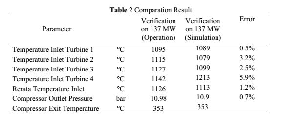
parameters as seen on table 1.


The result of comparation between operating and simulation condition shown that the temperature
on inlet turbine from four point of calculation gave arround 1% until 5% of error as shown on table 4.2.
This lead that the geometry check has similarity with operating condition.


The simulation’s result the temperature outlet of combustion chamber has similarity compared to
operation condition. Methane is a fuel gas contain that used as the reference of this analysis. Since the
actual composition during operating of the Muara Tawar’s gas turbine couldn’t accurately calculate (no
gas chromatograph to sense mixing gas) there were three gas classification, high composition (CH4
94%), medium (CH4 87%) and low (CH4 71%).
3. Result and discussion
3.1 Flame Stability
The flame length is one of the stability parameters combustion mechanism which closely related to
the mixing of fuel and air. The increasing of flame length indicated the combustion happened away from
the burner tip and tend to flame becomes unstable. The combustor design that applied the air swirl help
to increase the combustion intensity and reduce the flame length. Swirl flow also provided an angular
velocity to the axial incoming flow to produce a central recirculation zone (CRZ) which provides the
main flame stabilization.


As seen on figure 1 the flame length combustion with fuel with a methane content of 94% produces the
longest flame length arround 4.7 m from burner tip. Amer and Gad [4] studied experimentally the effect  of increasing air to fuel ratio on experimental study of LPG combustion. Increasing the air to fuel mass
ratio (excess air) from 5% to 20%, the flame length decreases by about 6% to 16%. The flame length
that indicated the lift will be stabilized by inner recirculation zone.


Recirculation zone on figure 2 showed the negative axial velocity in the center of the combustion
chamber indicates the presence of an inner recirculation zone due to circulating air flow made by swirl
air inlet which results in a vortex breakdown process and initiates a recirculation zone in the center of
the combustion chamber. The composition of the fuel with a higher methane content results in a wider
circulation zone when compared to fuel with a lower methane content as seen on figure 2. The length of
recirculation about 3.4 m and for low methane reached 2.1 m. The result of analysis clearly explain on
figure 3 that calculate on each gas composition and excess air.


The addition of excess air changes the characteristics of the recirculation zone, the more excess air
resulting in shorter recirculation center distances with a larger recirculation zone area. Hong, et al [5]
made some study on recirculation zone as excess air raised. The higher temperature of the products
reduces the velocity gradient in the shear layer and thus the reattachment length. The addition of 5%
excess air reaching 504 kg/s resulted in a recirculation center distance of 2.38 m from the burner tip.
3.2 Temperature Distribution
Combustion process is a reaction between fuel gas and oxygen in the air. The result of this process
were carbon dioxide (CO2), water (H2O), and a great deal of energy. The higher methane content, the
higher the maximum temperature reached. The length of maximun temperature also increases from the
tip burner. The addition of excess air as showed on figure 4 shows that as the amount of air increases,
the temperature to the outlet will decrease this is due to the combustion losing a certain amount of energy
because too much air enters the combustion chamber.


The addition of excess air from 15% to 20% does not cause a significant increase in maximum
temperature and energy. The combustion efficiency increases with increased excess air until the heat
loss in the excess air is larger than the heat from combustion. Munir et al [6] evaluate the effect of excess
air on combustion concluded that an optimum air fuel ratio should be maintained to ensure complete
combustion as well as to decrease the excessive losses due to surplus air.
3.3 NOx Emission Characteristic
Nox emission is produced by the oxidation of atmospheric nitrogen in high temperature regions of
the combution flame and postflame gases at the outlet. Previously reported sitgnificant effects on NOx
characteristic by Thomson, et al [6] that the nitric oxide formation rate in post flame gases of
hydrocarbon flames (T > 1800°K) and follows the Zeldovich chain mechanism. The combustion process
will lead the creation of nitrogen oxides from nitrogen from air or gas fuel. At higher temperatures both
can react to form NOx in large quantities. The formation of the NOx mass fraction in combustion with
variations in the methane content shows a higher value due to ethane increasesing as shown in figure 5.


The addition ofexcess air in combustion will also affect the reaction of NOx mass fraction as a result
of combustion temperatures that becone lower. This is the point that the excess air become too much.
as excess air.
4. Conclusion
The analyses were carried out for combustion characteristic for gas turbine type V94.2 using several
composition of natural gas that being used as fuel in Muara Tawar power plant. Through the numerical
simulations it was possible to notice that:
The more flame lenght on Fuel with a greater methane content results the flame lenght increasing
and tend to unstable combustion.
The CRZ distance is about 3.4 m and with a methane content of 94% and the more excess air will
lead the CRZ becomes shorter but the area of recirculation become wider.
The addition of excess air causes the temperature to decrease at the outlet area of the combustion
chamber due to combustion losing some energy because too much air enters the combustion chamber.
Temperature plays an important role in the formation of the mass fraction of NOx, the lower the
temperature the less mass fraction of NOx is produced.
The addition of excess air of about 5% provides the most optimal combustion stability and emission
factor values.
The results of the analysis clearly demonstrate that it is possible to use such fuels in combustion
systems with swirl burners.


Friday, May 13, 2022

Carbon Capture & Storage


Carbondioxide Capture and Storane (CCS) merupakan salah satu mitigasi adanya pemanasan global dengan cara mengurangi emisi CO2. Teknologi CCS merupakan rangkaian pelaksanaan proses yang terkait satu sama lain, mulai dari pemisahan dan penangkapan (capture) CO2 dari sumber emisi gas buang (flue gas), pengangkutan CO2 yang tertangkap ke tempat penyimpanan (transportation), dan penyimpanan ke tempat yang aman (storage). 


CSS memiliki potensi untuk mengurangi keseluruhan biaya mitigasi dan meningkatkan upaya pengurangan emisi gas penyebab efek rumah kaca. Penerapan teknologi CSS akan sangat tergantung pengembangan teknologi yang semakin feasible, potensi penerapan dan pengaplikasian, biaya, transfer teknologi antar negara, aspek peraturan, isu lingkungan dan adanya persepsi atau cara pandang masyarakat. Emisi gas rumah kaca dihasilkan paling besar akibat aktivitas manusia berupa pembakaran bahan bakar fosil, biomass, pembakaran lahan dan aktivitas industry lain.
Emisi dari gas rumah kaca sendiri adalah gas-gas di atmosfer yang dapat menimbulkan perubahan dalam kesetimbangan radiasi (daya pantul maupun daya serap pada atmosfer) sehingga mempengaruhi suhu atmosfer dan juga permukaan bumi. Gas-gas tersebut dinamakan gas rumah kaca karena kemampuannya dalam menyerap dan memantulkan kembali radiasi gelombang panjang yang bersifat panas seperti yang dilakukan oleh kaca, sehingga menimbulkan efek pemanasan global yang disebut efek rumah kaca.
Karbondioksida berkontribusi sebesar 76,7% dari total emisi gas rumah kaca dan di tahun 2000 emisi CO2 akibat pembakaran bahan bakar fosil mencapai 23,5 GtCO2 terutama dihasilkan oleh industry energi seperti dalam table 1.


Peningkatan emisi CO2 dari tahun 1971 hingga 2001 menunjukkan peningkatan seiring dengan peningkatan pemakaian sumber energi dari fosil yang semakin dominan dan mencapai angka 86% dari total pemakaian di seluruh dunia.
Tabel 1. Tingkat Emisi dari Pembakaran Bahan Bakar Fosil
Emisi terbesar dari sector pembangkitan energi berasal dari batu bara yang mencapai 59% atau setara dengan total emisi sebesar 7.984 MtCO2 pertahun (data tahun 2002) secara rinci emisi CO2 yang dihasilkan dari sector energi terdapat dalam table 2 berikut;

 Tabel 2. Emisi dari sector pembangkit energi

Pemanfaatan teknologi untuk mengurangi emisi CO2 ke atmosfer terdiri dari beberapa pendekatan yang meliputi :
  • Mengurangi konsumsi energi bahan bakar, contohnya dengan meningkatkan efisiensi dari konversi energi.
  • Beralih penggunaan bahan bakar dengan kandungan karbon yang lebih rendah, seperti penggunaan gas dibanding batu bara.
  • Peningkatan penggunaan energi terbarukan atau energi nuklir yang menghasilkan emisi CO2 yang rendah atau tanpa emisi sekali.
  • Penangkapan gas CO2 secara biologi atau secara alami dengan meningkatkan kemampuan hutan dalam penyerapan CO2.
  • Teknologi menangkap dan menyimpan CO2 secara kimiawi dan metode fisis.
Teknologi penangkapan CO2 dan penyimpanan yang akan dibahas lebih lanjut bertujuan untuk menghasilkan gas yang terkonsentrasi sehingga memudahkan proses pemindahan CO2 ke tempat penyimpanan. Penangkapan CO2 akan optimal apabila dilakukan pada lokasi industry dan pembangkitan energi dimana dihasilkan emisi CO2 dalam jumlah yang banyak. Terdapat 4 teknologi dalam upaya menangkap emisi CO2 yang meliputi seperti dalam gambar 3 berikut
Berdasarkan gambar 3. di atas terdapat beberapa proses penangkapan gas buang CO2 yang dilakukan oleh industry di seluruh dunia, diantaranya adalah :
  • Menangkap CO2 dari proses industry, salah satunya dikenal dengan metode sweetening yaitu mengurangi kandungan CO2 dalam gas alam.
  • Teknik post-combustion, menangkap CO2 dari gas buang pembangkit listrik setelah   bahan bakar fosil dibakar. Gas buang akan melewati absorber tower yang mempunyai bahan kimia khusus (biasanya amina). Amina berfungsi untuk menyerap CO2 dari gas buang
  • Teknik pre-combustion biasanya diterapkan pada Integrated Gasification Combine Cycle (IGCC) yaitu pembangkit listrik tenaga batu bara dan penangkapan CO2 dilakukan sebelum batu bara benar- benar membara. Batu bara dipanaskan secara perlahan untuk mengeluarkan synthetic gas yang terdiri dari karbon monoksida dan hydrogen.
  • Teknik oxyfuel combustion yaitu membakar bahan bakar fosil dengan oksigen murni alih-alih dengan udara. Gas buang yang dihasilkan hampir seluruhnya terdiri dari CO2 dan air. Air dikeluarkan melalui kondensasi sedangkan CO2 dikompresi agar dapat dipindahkan. Tehnik ini dapat menghasilkan tingkat penangkapan CO2 yang sangat tinggi, kekurangannya metode ini membutuhkan banyak energy untuk menghasilkan oksigen murni sehingga relative tidak efisien.
Dari penjelasan di atas kemudian dalam tulisan ini akan dirangkum dua jenis teknologi yang secara umum digunakan oleh industry diantaranya adalah teknologi pre combustion dan post combustion.


Tuesday, January 25, 2022

Optimization of Prefill Mode to Increase Reliability of Gas Turbine 13E2 PT. PJB UP Muara Tawar

IOSR Journal of Mechanical and Civil Engineering (IOSR-JMCE). e-ISSN: 2278-1684,p-ISSN: 2320-334X, Volume 14, Issue 3 Ver. VII. (May - June 2017), PP 13-18. www.iosrjournals.org

Abstract: Muara Tawar block V is constructed by PT. PLN (Persero) Power Plant Master Project ofJava, Bali and Nusa Tenggara Networks based on contract No. 261. PJ / 041 / DIR / 2007 (Concerning Gas-Fired Power Plant Extension Project). The plant uses gas turbine type 13E2. The operational concept of gas turbine type 13E2 is regulating the amount of fuel that is divided from three fuel control valves and the operating pattern is in an area known as the pilot valve and premix valve which must be maintained the stability of combustion shown by pulsation parameters. The prefill concept is used to avoid flame off when gas turbine loading often passes over point switch or back point switch. Prefill itself will momentary activate a pilot valve to fill the Fuel Distribution System (FDS) line from MBP43. However, prefill gives the effect of high pulsation that triggers Gas Turbine experience PLS or derating. This effect can be overcome by improving the prefill concept and modifying the prefill system through Logic Advant, resulting in a more stable burning in the gas turbine burner.
Keywords: Gas-Fired Power Plant, FDS, pilot valve, pulsation, prefill.


I. Introduction
The utilization of gas turbines in power generation has increased in recent years and it will be increased up to a medium level of application [1]. Muara Tawar Block V gas turbine system was designed to operate at peak or under load continuously in both open and combined cycles as per network requirement. Muara Tawar Block V power generation can generate 242.5 MW electricity (gross output). It comes from the gas turbine generator alone about 161.5 MW and from the steam turbine is about 81 MW [2]. The reliability of a power plant to
provide electricity to the electricity network is the most important task to ensure energy availability [3]. Gas Turbine type 13E2 consist of three fuel control valves to maintain mass and energy balances in the burner system under the pilot and premix valve. To maintain stable combustion, changes in the operating condition between the pilot valve and the premix valve are required and it's known as switch over and switch back point. During these conditions, the pulsation parameter should be monitored. If the gas turbine operates in high load or above switch over point continuously, it tends pilot valve MBP43 cannot provide sufficient gas fuel to the combustion system. Moreover, during the load decrease, the operating condition will change to a switchback point. It condition leads to mass unbalance and it can be very dangerous because the pilot valve must close immediately. Moreover, in this condition, the pilot valve status is closed due to operation in high load. This condition triggers flame off resulting in the unit trip. The prefill concept is used to overcome this hazard and unscheduled shut down by the pilot valve in the MBP43 area pulse opening. However, prefill can also affect the emergence of high pulsation that resulted in gas turbines experiencing PLS or derating.

II. Theory
Prefill is used to reduce the disturbance that may arise due to the changing of electricity load from high to low load and vice versa. Prefill is used to fill up the volume between Fuel Distribution System (FDS) to the burner [4]. This prefill is performed by opening the pilot valve or MBP43 at a certain time to ensure the volume of the FDS until the burner fills up with approximately 20% of additional fuel. Mass unbalance occurs when the load is over the SwitchBack Point (SBP) area. Therefore, the prefill on the FDS pilot will not cause the flame off when SBP is present.


The prefill will be activated when the decrease in electricity load occurs. The prefill system will open the MBP43 control valve from the minimum mass flow rate and increase up to the maximum mass flow rate gradually to fill up the volume between FDS to the burner. The gas turbine at Muara Tawar Block V mass flow rate was designed at 0.285 kg/s in maximum load and 0.250 kg/s in minimum load [5]. The prefill process will stop if any of the criteria are reached i.e. Delta TAT (Temperature After Turbine difference) reaches 5 deg C or high pulsation reaches 35 mbar, or maximum prefill time has reaches 10 seconds.

III. Method
3.1 Analyze DEPP Prefill System of Gas Turbine
Logic prefill system is simulated under Advant Egatrol 8 software. Simulation on the logic includes the operation of pilot valve MBP43 and the operating pattern of the prefill system.


Fig. 2. describes prefill system, where prefill will be enabled or start (PltPrfSqPrel_START) with 2

modes i.e. periodically time (PltPrfSeqCyc_START) or decrease in load. Every 4 hours, the gas turbine will experience periodic prefill at any load that causes interruption to Protective Load Shedding (PLS). Interruption to PLS by high pulsation is caused by an over mass flow rate from MBP43 or pilot valve.

Fig. 3. shows the high pulsation which resulted in PLS 148 mbar. High pulsation occur because MBP43 

(number 4) is activated and mass flow rate or gas fuel flow rate of 0.250 kg/s up to 0.285 kg/s during 10 seconds. This logic set can be observed in Fig. 4. Periodic prefill is set up for every 4 hours which often results in high pulsation. Total mass flow rate can be obtained in two ways i.e. the mass flow rate on the scale is too large or the setting time is too long for each prefill process.

3.2. Fix the Prefill Function on the Operational Concept from the Advant logic side
Based on the investigation of the logic prefill compared to the DEPP data trending it is necessary to make some parameters modification that will affect the prefill process as well as Prefill operation pattern. Improvement of the prefill logic is done in several stages. The first stage is to modify the maximum time for each prefill (TIME_MAX_PRF_C1). The maximum time for prefill is gradually lowered and applied directly when the gas turbine operates by monitoring DEPP trending data continuously.


Based on Table 1. It can be seen that a decrease in setting time will reduce the pulsation that occurs in the burner. However, the maximum limit of changes is shown by the absence of diff TAT. Diff TAT indicates that the prefill has perfectly filled the FDS. The maximum prefill time decrease gradually and reaches the optimum value of 7 seconds. However, a change in time setting is not the best choice because the gas turbine is still experiencing PLS due to prefill for a while. The next step is decreasing the pilot valve mass flow rate value in logic prefill shown by Fig. 6. The mass flow rate value decreases gradually while pulsation pattern and changes in TAT are continuously observed.
Changing of pilot valve mass flow rate parameters compared to the pulsation values can be observed in Table 2.

Any decrease in mass flow rate will result in a decrease of high pulsation value. However, the maximum limit of changes is indicated by the absence of diff TAT. Change in mass flow rate value obtained minimum high pulsation at the point of 0.2 kg/s for both minimum and maximum mass flow rate.

IV. Results And Discussions
Prefill system on turbine gas will help avoid flame off when there is a change in the area of switch over or switchback point. However, the active prefill will cause high pulsation so PLS or Protective Load Shedding will be active. PLS will cause turbine gas load to drop until a normal condition is reached and PLS is reset.


In Fig. 7. There is an active PLS signal from signal number 7 that is 51MBX41EA000_XU03 PLS 2oo3 or PLS 2 out of 3 active signals. PLS is active because of signal high pulsation number 9, 51MBM30AX010Breach 148 mbar. High pulsation reaching 148 mbar would cause PLS. PLS always happens when prefill process takes place. The total event for 2012 is 52 times starting from February 10, 2012 and the last event is November 7, 2012. High pulsation results in PLS because Prefill occurs in an area of about 60% to 65% Relative Power or approximately 112 MW. The operating load in 112 MW is the demand from the network at certain times. However, if prefill operates at a relatively high load (above 120 MW), then the prefill process will not cause high pulsation because the proportion of premix is so large that the effect of the prefill is relatively small. Using this information, logic improvements are needed by modifying the enabled function
PLT_PREFIL_CYC_EN, so when turbine gas operates at a load the cyclic prefill will not be active. This function can be activated when a gas turbine operates with a relatively high load. 
When under load, the prefill will be active when the gas turbine experiences a minimum load loss of 0.35 MW/s for 10 seconds. Fig. 10. show prefill process after modifying function has been done. Prefill occurs when the Gas Turbine experiences a decrease in load from 143 MW to 113 MW within 2 seconds or a decrease of 15 MW per second. This prefill occurs optimally by being marked by a small power swing and no increase in pulsation value.

V. Conclusion
Fixing the prefill function from gas turbines can reduce and eliminate PLS due to High Pulsation. Prefill function improvement is done by disabling cyclic prefill function under load. With the improvement of prefill function, there is no more derating because of prefilling. Despite the improvement of the prefill system to the operational concept of gas turbine, monitoring of combustion parameters must continue.

Endrik Purbo Yunastyo1, Danan Tri Yulianto1, Asnawadi Hidayat1,
Kevin Sanjoyo Gunawan2, Totok R. Biyanto2*
1PT. PJB UP Muara Tawar, Muara Tawar, Indonesia
2
Engineering Physics Department, Institut Teknologi Sepuluh Nopember (ITS), Surabaya, Indonesia.